CS 4141 — Digital Systems Laboratory, Lab 1 — Pre-Lab
Logic Gates and Truth Tables
| A | NOT |
|---|---|
| 0 | 0 |
| 1 | 0 |
| A | B | AND | OR | NAND | NOR | XOR |
|---|---|---|---|---|---|---|
| 0 | 0 | 0 | 0 | 1 | 1 | 0 |
| 0 | 1 | 0 | 1 | 1 | 0 | 1 |
| 1 | 0 | 0 | 1 | 1 | 0 | 1 |
| 1 | 1 | 1 | 1 | 0 | 0 | 0 |
The Lab Station
Look at the image of the chassis on page 2, on the left side there are a few different power sources: +V, −5V, -V, +5V, GND. Which sources do you use to power and ground an IC (integrated circuit)?
We connect to the +5V hole and GND hole immediately to the left of each bus strip.
What are bus strips?
Bus strips are the rows of holes on the bottom and to the right of the IC board. These holes are used as the power source for various electrical components across the board.
Why are bus strips useful?
Because of their length, they make it easier to arrange electrical components along the board by allowing one to use short wires to power each component. Additionally, they allow easily connecting multiple connections to the same power source.
Is hole A1 connected to hole B1?
Yes
Is hole A3 connected to hole A5?
No
Is hole E5 connected to hole G5?
No
Is hole H1 connected to hole J1?
Yes
Reading Integrated Circuit Chip Pinouts
Is Pin 3 in the (7400) NAND chip an input or an output?
Output
Is Pin 3 in the (7402) NOR chip an input or an output
Input
Is Pin 11 in the (7404) NOT chip an input or an output?
Input
How many gates are in one (7408) AND chip?
4
What is pin 7 on the (7486) XOR chip?
GND
Draw a Truth Table for a Boolean Logic Equation
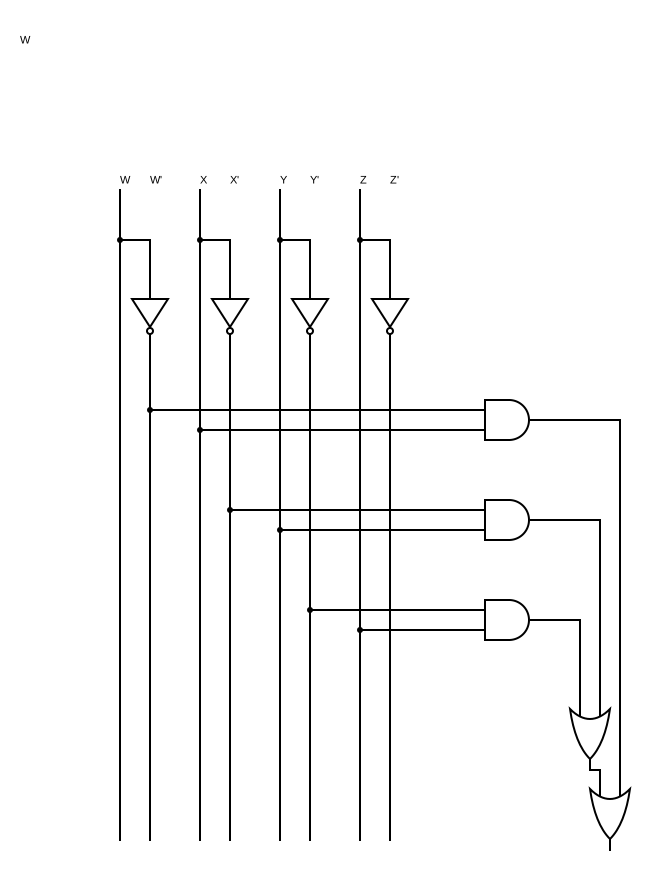
f(w, x, y, z) = w’x + x’y + y’z
| w | x | y | z | w’x | x’y | y’z | f |
|---|---|---|---|---|---|---|---|
| 0 | 0 | 0 | 0 | 0 | 0 | 0 | 0 |
| 0 | 0 | 0 | 1 | 0 | 0 | 1 | 1 |
| 0 | 0 | 1 | 0 | 0 | 1 | 0 | 1 |
| 0 | 0 | 1 | 1 | 0 | 1 | 0 | 1 |
| 0 | 1 | 0 | 0 | 1 | 0 | 0 | 1 |
| 0 | 1 | 0 | 1 | 1 | 0 | 1 | 1 |
| 0 | 1 | 1 | 0 | 1 | 0 | 0 | 1 |
| 0 | 1 | 1 | 1 | 1 | 0 | 0 | 1 |
| 1 | 0 | 0 | 0 | 0 | 0 | 0 | 0 |
| 1 | 0 | 0 | 1 | 0 | 0 | 1 | 1 |
| 1 | 0 | 1 | 0 | 0 | 1 | 0 | 1 |
| 1 | 0 | 1 | 1 | 0 | 1 | 0 | 1 |
| 1 | 1 | 0 | 0 | 0 | 0 | 0 | 0 |
| 1 | 1 | 0 | 1 | 0 | 0 | 1 | 1 |
| 1 | 1 | 1 | 0 | 0 | 0 | 0 | 0 |
| 1 | 1 | 1 | 1 | 0 | 0 | 0 | 0 |
Draw a Boolean Logic Gate-Level Circuit for the given equation. Let w be the most significant bit and z be the least significant bit, from left to right.